Arduino Switch Controller - finished
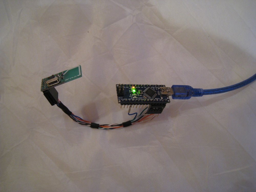 Well the steering wheel transmitter and dashboard are almost finished - now I need the wireless switch controller so it all works...
Previous blog on button upgrade gave the basic details - this is a continuation.
The heart of the switch controller is an Arduino Nano micro-controller - this is going to be the interface between the dashboard switches, wireless steering wheel buttons and the car's lighting, indicators, windscreen wipers and DigiDash2 GPS stopwatch.
So far, I have got a 2.4GHz transceiver working with the Nano - receives all the steering wheel button presses:
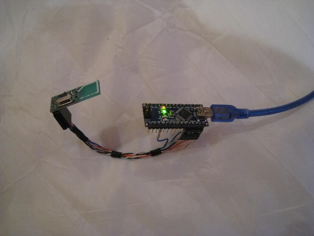
This should make it easy to have self-cancelling indicators, intermittent wipe, auto wipe on wash, plus can use multiple button presses to choose sidelight/ headlight or wiper speeds - any logic you like, really since its all software controlled. Also removes the need for any electronic hazard flasher or ballast resistors with LED lights, as the MOSFET should handle it all.
I've started on the wiring schematic for the controller - first time I've used MOSFETS, so should be interesting - any electronics enthusiasts please feel free to critique. ![]() I'm using the excellent (free) expressSCH software having previously drowned in untidy paper sketches...
I'm using the excellent (free) expressSCH software having previously drowned in untidy paper sketches...
Next step is to mount the voltage regulator and input/ output resistors on a stripboard and get the thing cased up, then put the transistors/ MOSFETS on a large heatsink that will attach beneath the scuttle somewhere and sort out the wiring mods to the Westield loom...
Here's an updated schematic that includes the circuit for low-side switching and component part numbers: I realised that it would be easy to use low-side switching on the wiper motor as the ground is accessible - the circuit is simpler and high current N-channel MOSFET's are cheap.
I'm going to start testing the circuits and writing the code this weekend hopefully... If I find anything wrong, I'll update the schematic in case anyone else plans to use it 
10/1/13 - tested all the circuits - no problems found, so I went ahead with the stripboard layout, about to start soldering up...
13/1/13 - stripboard finished, ordered a box and some pcb terminals to make it easy to wire in... Getting closer!
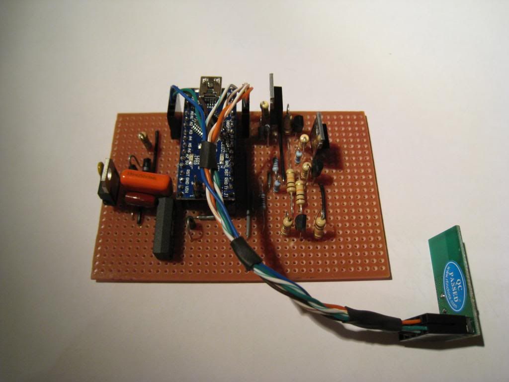
21/7/13 Distracted myself with some building projects at home, but back on the case now...
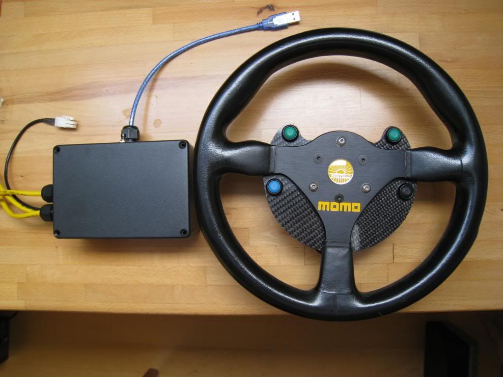
Added the pcb terminals and fitted to a case - ready for mounting in the car finally...

Arduino sketch
29/12/13 Finally finished! I made a few changes to keep hazard and sidelight circuits working with the ignition off- the Arduino effectively just replaces the indicator switch and controls dipped and main beam relay. I also added a reed switch with single magnet on the steering column to cancel the indicators. So a single indicator press will switch on for up to 15 sec if the steering doesn't move, but if the steering returns to straight ahead then I wait 3 secs and cancel. This should work well for roundabouts or side turns. Otherwise, pressing the button again will turn off, or pressing the other side button will switch direction. It would be really easy (and cheap) to just make a self cancelling indicator controller better than any you can buy using the same method - perhaps I should draw a kit up?
Final version of schematic and stripboard layout.
I had planned to use the hazard feed with diode as shown on the schematic earlier, but in the end decided it would be easier and safer to hard wire the hazards as 'normal' but then use the normal 'Lucus switch' live indicator feed to supply the Mosfets. This means that even if the Arduino fails, the hazards still work.
For the sidelight, I've hardwired it with a latching changeover Durite relay, so it always toggles on/off/on/off/on/off with a savage momentary switch (could also have used a latching switch with a standard relay which is cheaper). Then I sense the 12V relay changeover (so HIGH when sidelights off, LOW when on) and use this to cycle headlights on and off. So with ignition off you get sidelight on/off/on/off, but with ignition on you get side+head/off/side/off/side+head/off etc. If headlights are on then main beam latches on or off with each button press, otherwise main beam is just a 1s flash. Seems to work well...
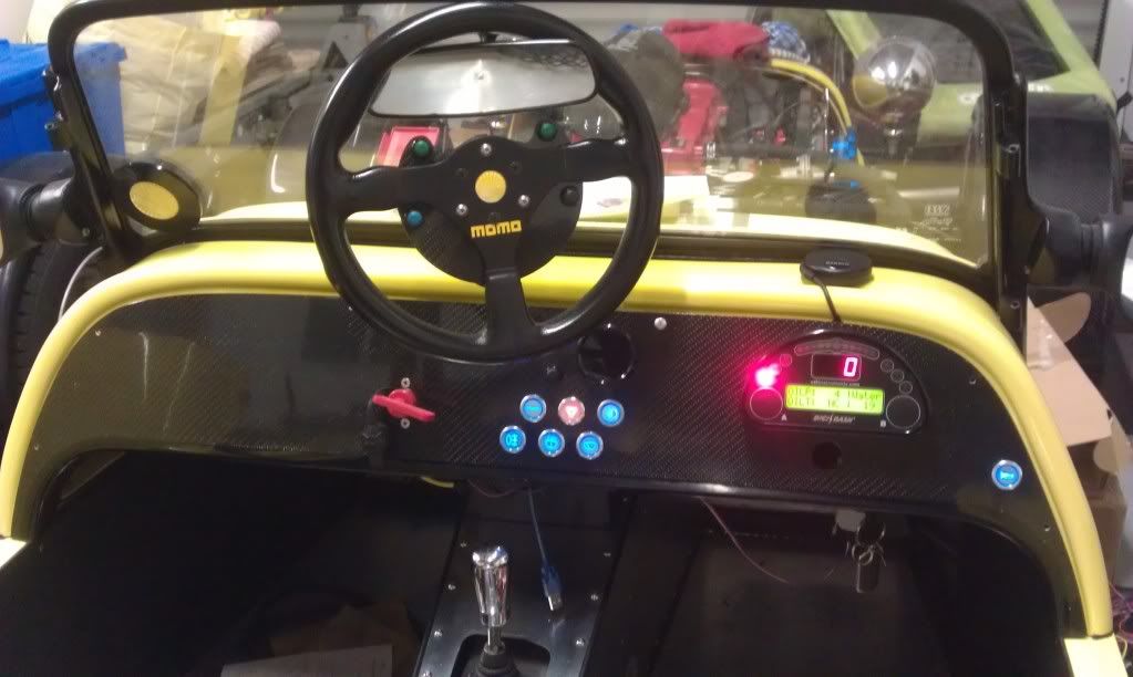
Dash nearly finished:
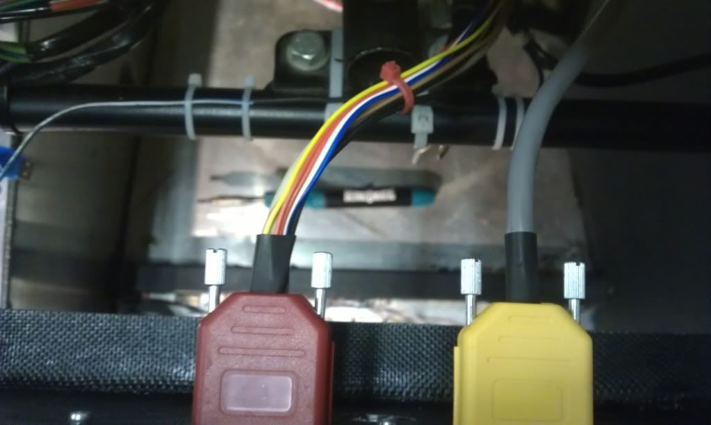
wiring about to be connected and tie wrapped – you can just see the reed switch inside heatshrink tied below the steering column top bracket.
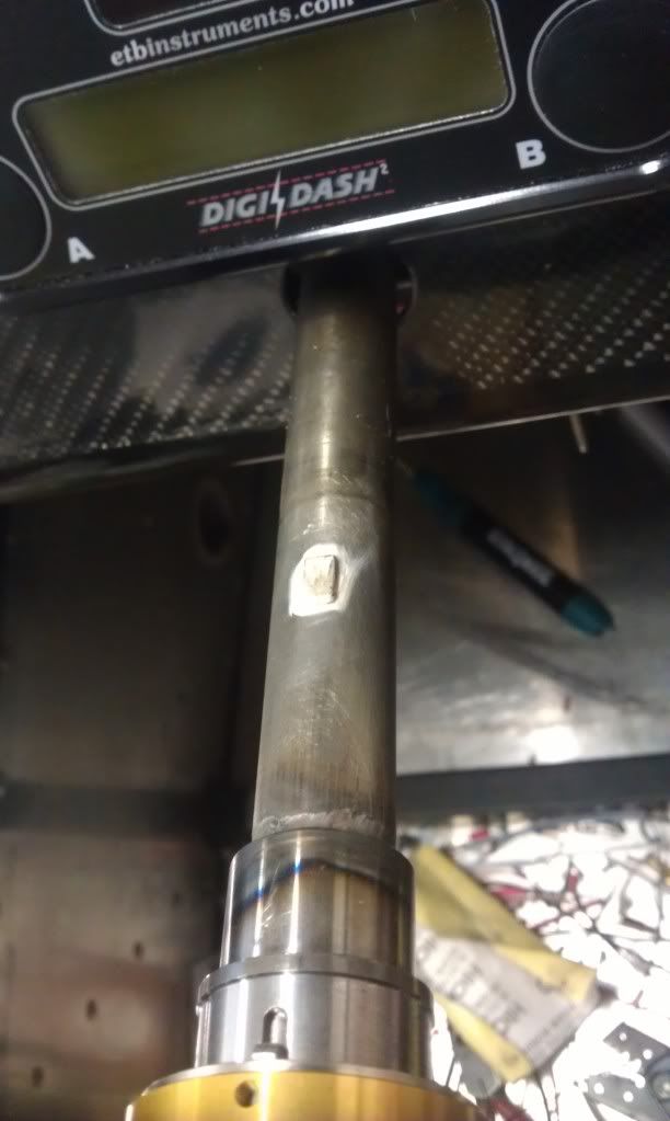
Then I have a strong small magnet (8x5x2mm) attached to the shaft so the switch is closed around the straight ahead position:
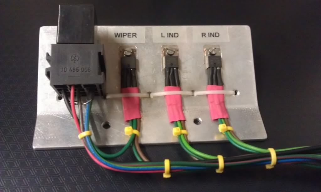
MOSFET’s and wiper park relay
It’s working perfectly – takes about 2 seconds to boot from ignition on, which is fine. I’ve added all the diodes and resistors for the Savage lights so they all work nicely too.


17 Comments
Recommended Comments